Application of light interference. Diffraction of light. (Presentation). Interference. presentation for a physics lesson (grade 11) on the topic Phenomena of interference and diffraction of waves download the presentation
To view the presentation with pictures, design and slides, download its file and open it in PowerPoint on your computer.
Text content of presentation slides: Presentation by the teacher of Municipal Educational Institution “Secondary School No. 56 with UIOP” in Saratov Sukhova Tatyana Mikhailovna Interference of light. Interference is the addition of two (or several) light waves, in which the light intensity increases at some points in space and weakens at others. Conditions for the coherence of light waves. Waves whose phase difference does not depend on time are called coherent. Manifestations in nature. Application of interference. The phenomenon of light interference is widely used in modern technology. One such application is the creation of “coated” optics. The phenomenon of mechanical waves bending around obstacles is observed when river waves freely bend around objects protruding from the water and spread as if these objects were not there at all. A phenomenon characteristic of all wave processes. Sound waves also bend around obstacles and we can hear a car signal around the corner of the house when the car itself is not visible. Lesson plan.1. Jung's experience.2. What is diffraction.3. Hugens' principle.4. Hugens-Fresnel principle.5. Diffraction patterns from various obstacles.6. Limits of applicability of geometric optics.7. Resolution of optical devices.8. Conclusion. In the mid-17th century, the Italian scientist F. Grimaldi observed strange shadows from small objects placed in a narrow beam of light. These shadows did not have clear boundaries and were bordered by colored stripes. Diffraction of light is the bending of a light wave around opaque bodies with penetration into the region of a geometric shadow and the formation of an interference pattern there. Christiaan Huygens played a major role in the development of the idea that the propagation of light is a wave process. Each point on the surface reached by a light wave is a secondary source of light waves. The envelope of the secondary waves becomes a wave surface at the next moment in time. Augustin Fresnel laid the foundations of wave optics, supplementing Huygens' principle with the idea of interference of secondary waves: he constructed a quantitative theory of diffraction. Each element of the wave front can be considered as the center of a secondary disturbance generating secondary spherical waves, and the resulting light field at each point in space will be determined by the interference of these waves. The diffraction of light manifests itself most clearly when this condition is met (diffraction observation condition). Where D is the size of the obstacle or hole, is the light wavelength, L is the distance from the obstacle to the place where the diffraction pattern is observed. l 2 D L Diffraction also places a limit on the resolving power of a telescope. The maximum angular distance () between luminous points at which they can be distinguished is determined by the ratio of the wavelength () to the lens diameter (D). Light diffraction is used to create sensitive spectral devices. Diffraction phenomena bring not only benefits, but also harm, limiting the resolution of optical instruments. II OPTION 1. B2. AT 3. B4. D5.6. D 7. G 1. A2. B3. A4. G5. 6. A7.A 1. What is diffraction?2. Formulate the Huygens principle.3.Formulate the Huygens-Fresnel principle.4. How to get a dark or light spot in the center of the diffraction pattern of a hole?5. Limits of applicability of geometric optics.6. Resolution of optical instruments. There is no separate interference and separate diffraction - this is a single phenomenon, but in certain conditions the interference properties are more prominent, in others - the diffraction properties of light. Myakishev G.Ya., Bukhovtsev B.B. Physics: textbook for 11th grade. – M.: Education Zhelezovsky B.Ya. Lectures on optics for SSU studentsEducational complexes. Physics, 7-11 grades, Library of visual aids Physikon programs, Physics 7-11 grades, Local version Kirill and Mifodiy, Educational electronic publications BENP Physics
Interference of mechanical waves. Wave addition
What happens to sound waves when
a conversation between several people while an orchestra is playing,
sings a choir, etc.?
What do we observe when we enter the water at the same time?
two stones fall
or drops?
Let's trace this on a mechanical model
We observealternation
light and dark
stripes
This means that
any point
surfaces
fluctuations
fold up. d1
d2
d
d1
d2
The amplitude of oscillations of the medium at a given point is maximum if the difference
the course of two waves exciting oscillations at this point is equal to an integer
number of wavelengths: Where k = 0,1,2...Minimum if an odd number
half-wave
dk
d (2k 1)
2
Interference.
Addition in the space of waves, which producestime-constant amplitude distribution
the resulting oscillations is called interference.
Coherent waves.
For the formation of sustainableinterference pattern
it is necessary that
the wave sources had
same frequency and
their phase difference
fluctuations were constant.
Sources satisfying
these conditions are called
coherent.
Interference of light
To obtain stable interferencepaintings need coordinated waves. They have to
have the same wavelength and constant
phase difference at any point in space.
Interference in thin films.
Thomas Young was the first to explainwhy thin films
painted in different colors.
Interference of light
waves - the addition of two waves,
as a result of which
there is a stable
amplification pattern over time
or weakening of light vibrations at various points
space.
Jung's experiment diagram
Observing interference in laboratory conditions
Interference maxima and minima
Interference maxima are observed inpoints for which the wave path difference ∆d is equal to
an even number of half-waves, or, what is the same, an integer
number of waves:
d 2k k ,
2
(k 0,1,2,3,...)
Amplitude of medium oscillations at a given point
is minimal if the difference in the path of two waves is equal to
an odd number of half-waves:
Bubble
Newton's rings
Plano-convex lens withvery small curvature
lies on glass
record. If her
illuminate
perpendicular
a bunch of homogeneous
rays then around the dark
system will appear in the center
light and dark
concentric
circles. Distance between
painted rings
depends on color; rings
red color stand each other
farther from each other than
blue rings. Rings
Newton can also
watch in passing
light. Colors in passing
light are
complementary to colors
in reflected light. If placed between
plate and lens
some liquid then
ring position
will change (ρ will become
less). From attitude
both values of λ for
same color (same
frequency) can be determined
speed of light in liquid.
Diffraction is a deviation from the rectilinear propagation of waves.
Diffraction of light waves
Jung's experienceFresnel's theory.
Wave surface at any timerepresents not just the envelope of secondary waves, but
the result of their interference. View through nylon,
organza
Round hole
Round screen Diffraction grating, optical device,
representing
collection of large
number of parallel
equidistant from each other
friend of strokes
same shape
applied on a flat
or concave optical
surface.
The distance through which the lines on the grating are repeated is called the period of the diffraction grating. Denoted by the letter d. If
the number of strokes (N) per 1 mm is knownlattice, then the lattice period is found by the formula: d = 1 / N mm.
Diffraction grating formula:
Where
–
–
–
–
- corner
d - grating period,
α - maximum angle
of this color,
k - order
maximum,
λ - wavelength.

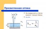
- A thin film is applied to the glass surface


Coated optics
The reflection of light for the extreme parts of the spectrum - red and violet - will be less. The lens has a lilac tint.


- Deviation of the direction of wave propagation from straight line at the boundary of an obstacle (waves bending around obstacles)
- Condition: the dimensions of the obstacle must be comparable to the wavelength


Grimaldi experience
- In the mid-17th century, Italian scientist Francesca Maria Grimaldi observed strange shadows from small objects placed in a very narrow beam of light. To the scientist’s surprise, these shadows did not have sharp boundaries, but for some reason were bordered by colored stripes.

Observation conditions
- - the size of the obstacle must be commensurate with the length of the light wave
- - the distance from the obstacle to the observation point must be much greater than the size of the obstacle

As a result of diffraction, light waves coming from different points are superimposed (coherent waves), and it is observed interference waves


Diffraction manifests itself in a violation of the straightness of light propagation!

Huygens' principle Fresnel
- Each point on the wave front is a source of secondary waves, and all secondary sources are coherent.

- Fresnel proved the linear propagation of light and quantitatively examined diffraction by various types of obstacles.


Peculiarities
diffraction pattern
Explanation
Slit image dimensions
more sizes,
received through
geometric
constructions
Secondary waves go behind
edges of the slit

Peculiarities
diffraction pattern
Explanation
In the center of the picture appears
light stripe
Secondary waves in
direction,
perpendicular to the slit,
have the same
phase. Therefore, when they
superimposed amplitude
fluctuations increase

Features of diffraction
Explanation
Along the edges of the picture - alternation
light and dark stripes
Secondary waves interfere
in a direction at an angle to
perpendicular to the slot,
having a certain phase difference, from
which the resulting
vibration amplitude


- Diffraction prevents clear images of small objects because light bends around objects.
- Images appear blurry. This occurs when the linear dimensions of objects are less than the wavelength of light.

Resolution of microscope and telescope
If two stars are at a small angular distance from each other, then these rings overlap each other, and the eye cannot distinguish whether there are two luminous points or one.

The phenomenon of interference occurs when two or more waves of the same frequency, propagating in different directions, interact. Moreover, it is observed both in waves propagating in media and in electromagnetic waves. That is, interference is a property of waves as such and does not depend either on the properties of the medium or on its presence. Interference

A stable pattern of alternating maxima and minima of oscillations of points in the medium when coherent waves are superimposed Coherent waves are waves of the same frequency with a constant phase difference Interference We encounter interference phenomena quite often: the rainbow color of oil stains on asphalt, the color of freezing window glass, fancy colored patterns on the wings Some butterflies and beetles are all manifestations of light interference.

Diffraction The phenomenon of diffraction occurs when complex light is decomposed. The position of the maxima and minima that make up the diffraction pattern depends on the wavelength of the light. Therefore, when observing in complex light, for example in white, where different wavelengths are represented, the diffraction maxima for different colors will be in different places.


Diffraction The phenomenon of diffraction imposes restrictions on the application of the laws of geometric optics: The law of rectilinear propagation of light, the laws of reflection and refraction of light are satisfied quite accurately only if the size of the obstacles is much larger than the light wavelength. Diffraction imposes a limit on the resolution of optical instruments: - in a microscope, when observing very small objects, the image turns out to be blurry - in a telescope, when observing stars, instead of an image of a point, we get a system of light and dark stripes.

Dispersion Wave dispersion is the difference in phase velocities of waves depending on their frequency. Wave dispersion leads to the fact that a wave disturbance of an arbitrary non-harmonic shape undergoes changes (disperses) as it propagates. Sometimes wave dispersion is understood as the process of decomposing a broadband signal into a spectrum, for example, using diffraction gratings.

Dispersion Red sunset, one of the results of the decomposition of light in the Earth's atmosphere. The reason for this phenomenon is the dependence of the refractive index of the gases that make up the earth's atmosphere on the wavelength of light. The rainbow, whose colors are determined by dispersion, is one of the key images of culture and art. Thanks to light dispersion, it is possible to observe the colored “play of light” on the facets of a diamond and other transparent faceted objects or materials. To one degree or another, rainbow effects are found quite often when light passes through almost any transparent object. In art they can be specifically intensified and emphasized.

Polarization A polarized wave is a transverse wave in which all particles oscillate in the same plane. Such a wave can be obtained using a rubber cord if a barrier with a thin slit is placed in its path. The slit will only allow vibrations that occur along it.


Malus's Law Linearly polarized light can be observed, for example, in laser radiation. Another way to produce linearly polarized light is to pass natural light through a Polaroid (polarizing filter), which freely transmits the component of light polarized along the selected direction and completely absorbs light with perpendicular polarization. If a linearly polarized wave is incident on such a polaroid, then the intensity I of the transmitted light will depend on the angle a between the direction of polarization of the incident light and the selected direction of the polaroid itself as follows: I = I 0 cos 2 a

Ellipsometry Ellipsometry is a set of methods for studying the surfaces of liquid and solid bodies based on the state of polarization of the light beam reflected by this surface and refracted on it. Plane polarized light incident on the surface acquires elliptical polarization upon reflection and refraction due to the presence of a thin transition layer at the interface. The relationship between the optical constants of the layer and the parameters of elliptically polarized light is established based on Fresnel formulas. Methods for sensitive non-contact studies of the surface of liquids or solids, adsorption processes, corrosion, etc. are based on the principles of ellipsometry.


Slide 2
Interference of light
- Interference is one of the most convincing evidence of wave properties.
- Interference is inherent in waves of any nature.
- Interference of light waves is the addition of two coherent waves, as a result of which an increase or decrease in the resulting light vibrations is observed at different points in space.
Slide 3
Coherent waves
- To form a stable interference pattern, the wave sources must be coherent.
- Waves that have the same frequency and a constant phase difference over time are called coherent.
- All light sources, except lasers, are incoherent.
Slide 4
How can we observe the interference of light?
- To observe the interference of light, it is necessary to obtain coherent light beams.
- To do this, before the advent of lasers, in all instruments for observing the interference of light, coherent beams were obtained by dividing and subsequent convergence of light rays emanating from a single light source.
- For this, slits, mirrors and prisms were used.
Slide 5
Jung's experience
- At the beginning of the 19th century, the English scientist Thomas Young conducted an experiment in which the phenomenon of light interference could be observed.
- Light passed through a narrow slit fell on two closely spaced slits, behind which there was a screen.
- Instead of the expected two light stripes, alternating colored stripes appeared on the screen.
Slide 6
Jung's experiment diagram
Slide 7
Observing interference in laboratory conditions
Slide 8
Interference maxima
Interference maxima are observed at points for which the wave path difference ∆d is equal to an even number of half-waves, or, what is the same, an integer number of waves.
Slide 9
Interference minima
Interference minima are observed at points for which the wave path difference ∆d is equal to an odd number of half-waves.
Slide 10
Interference in thin films
We have observed the interference pattern many times when we observed soap bubbles, the iridescent colors of a thin film of kerosene or oil on the surface of water.
Slide 11
Explaining interference in thin films
- A combination of waves occurs, one of which is reflected from the outer surface of the film, and the second from the inner.
- The coherence of waves reflected from the outer and inner surfaces of the film is ensured by the fact that they are parts of the same light beam.
Slide 12
Thin Film Color Explanation
- Thomas Young explained that differences in color are due to differences in wavelength (or frequency of light waves).
- Light beams of different colors correspond to waves of different lengths.
Slide 13
For mutual amplification of waves that differ from each other in length (the angles of incidence are assumed to be the same), different film thicknesses are required.
Slide 14
Therefore, if the film has unequal thickness, then when illuminated with white light, different colors should appear.
Slide 15
Newton's rings
A simple interference pattern occurs in a thin layer of air between a glass plate and a plane-convex lens placed on it, the spherical surface of which has a large radius of curvature.
Slide 16
The interference pattern has the form of concentric rings.
Slide 17
Explanation of "Newton's rings"
- Wave 1 is reflected from the bottom surface of the lens, and wave 2 is reflected from the surface of the glass lying under the lens.
- Waves 1 and 2 are coherent: they have the same length and a constant phase difference, which occurs because wave 2 travels a longer distance than wave 1.
Slide 18
Determination of the radius of Newton's rings
- If the radius of curvature R of the lens surface is known, then it is possible to calculate at what distances from the point of contact of the lens with the glass plate the path differences are such that waves of a certain length λ cancel each other out.
- These distances are the radii of Newton's dark rings, since the lines of constant thickness of the air gap are circles.
Slide 19
Wavelength Determination
Knowing the radii of the rings, you can calculate the wavelength using the formula, where R is the radius of curvature of the convex surface of the lens (k = 0,1,2,...), r is the radius of the ring.
Slide 20
Diffraction of light
Diffraction of light is the deviation of a wave from rectilinear propagation when passing through small holes and the wave bending around small obstacles.
Slide 21
Diffraction condition
where d is the characteristic size of the hole or obstacle, L is the distance from the hole or obstacle to the screen.
Slide 22
Observation of light diffraction
Diffraction causes light to penetrate into a geometric shadow region
Slide 23
Relationship between wave and geometric optics
- One of the basic concepts of wave theory is the wave front.
- The wave front is a set of points in space to which the wave has currently reached.
Slide 24
Huygens' principle
Each point in the medium to which a wave reaches serves as a source of secondary waves, and the envelope of these waves represents the wave surface at the next moment in time.
Slide 25
Explanation of the laws of reflection and refraction of light from the point of view of wave theory
- Let a plane wave fall at an angle onto the interface between two media.
- According to Huygens' principle, each point of this boundary itself becomes a source of spherical waves.
- The waves traveling into the second medium form a refracted plane wave.
- The waves returning to the first medium form a reflected plane wave.
Slide 26
Reflection of light
- The front of the reflected wave BD forms the same angle with the interface between the two media as the front of the incident wave AC.
- These angles are equal to the angles of incidence and reflection, respectively.
- Therefore, the angle of reflection is equal to the angle of incidence.
Slide 27
Light refraction
- The front of the incident wave AC makes a larger angle with the interface between the media than the front of the refracted wave.
- The angles between the front of each wave and the interface between the media are equal to the angles of incidence and refraction, respectively.
- In this case, the angle of refraction is less than the angle of incidence.
Slide 28
Law of light refraction
- Calculations show that the ratio of the sines of these angles is equal to the ratio of the speed of light in the first medium to the speed of light in the second medium.
- For these two environments this ratio is constant.
- This implies the law of refraction: the ratio of the sine of the angle of incidence to the sine of the angle of refraction is constant for these two media.
Slide 29
Physical meaning of the refractive index
The absolute refractive index is equal to the ratio of the speed of light c in a vacuum to the speed of light v in a given medium.
Slide 30
Conclusion
The laws of geometric optics are consequences of the wave theory of light, when the light wavelength is much smaller than the size of obstacles.
View all slides